Hull design
Introduction
Since the 2011-2012 season, the team has a new hull. Several reasons led us to change it. Among those reasons, the previous shell was old and cracked after 4 years of faithful service. Also, new projects (new tires, wheel covers integration and camber change) were brought and required some changes in the shape of the hull. In addition, the possibility of using the "Colosse", the supercomputer at Laval University, gave the team the opportunity to conduct extensive numerical simulations using CFD software (Computational Fluid Dynamics), this which suggested that it was possible to improve the aerodynamic performance of the vehicle by iterating on several models.
Objectives
The new tires the team wanted to use are specifically designed for competitive Supermileage and cause less loss by rolling than the previous tires. However, these new tires are wider by about a centimeter compared to the old ones. The previous hull was too narrow for the old tires to be used. One of the objectives in the design of the new hull was to make possible the use of our new tires. In addition, attention was paid to the space available at the front wheels to incorporate structural inner wheel covers.
It was proposed to reduce the camber of the wheels, the angle at which the wheels tilt inward of the vehicle. The angle was 8 degrees on the old hull. This allowed rounding of the general shape of the vehicle. In addition, due to competition rules wishing that the wheelbase is 50 centimeters at least, this was the best way to reduce the frontal area of the vehicle. However, with the new car, we wanted to introduce wider front tires and wheel covers. Thus, to maintain the angle of 8 degrees, ensuring that the driver has enough space, a wheelbase of around 60 centimeters is required. It was then proposed to reduce the camber to 1.5 degrees. This had the effect of allowing us to reduce the wheelbase to approximately 55 centimeters and thus reduces the frontal area. Also, the more the wheels are straight; most losses due to tire rolling will be lowered, as shown by tests performed by the renowned team PAC-Car (ETH Zurich). Thus, losses due to rolling friction are reduced of about 10% by decreasing the angle of inclination of the wheels from 8 degrees to 1.5 degrees. You should know that a large part of the losses of the vehicle comes from the friction of the wheels.
It was also desired to improve the accessibility to the engine compartment by enlarging it and lowering the cutting of the hood.
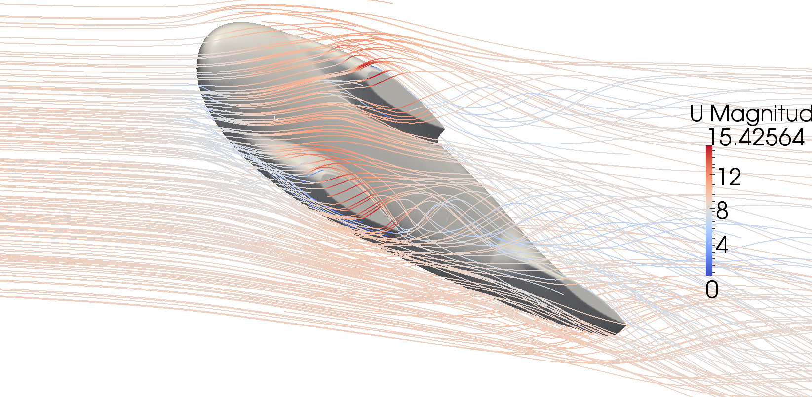
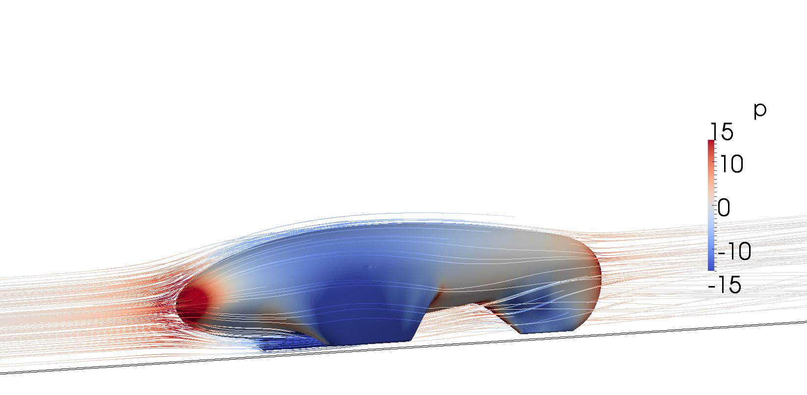
Obviously, the team also aimed to improve aerodynamics. To do this, the goal was to start by trying to get a form similar to the old hull and perform various changes by analyzing the impacts of these changes with numerical simulations.
Results
Although the old hull and the new model have a similar appearance in general, all the objectives listed above have been met with success.
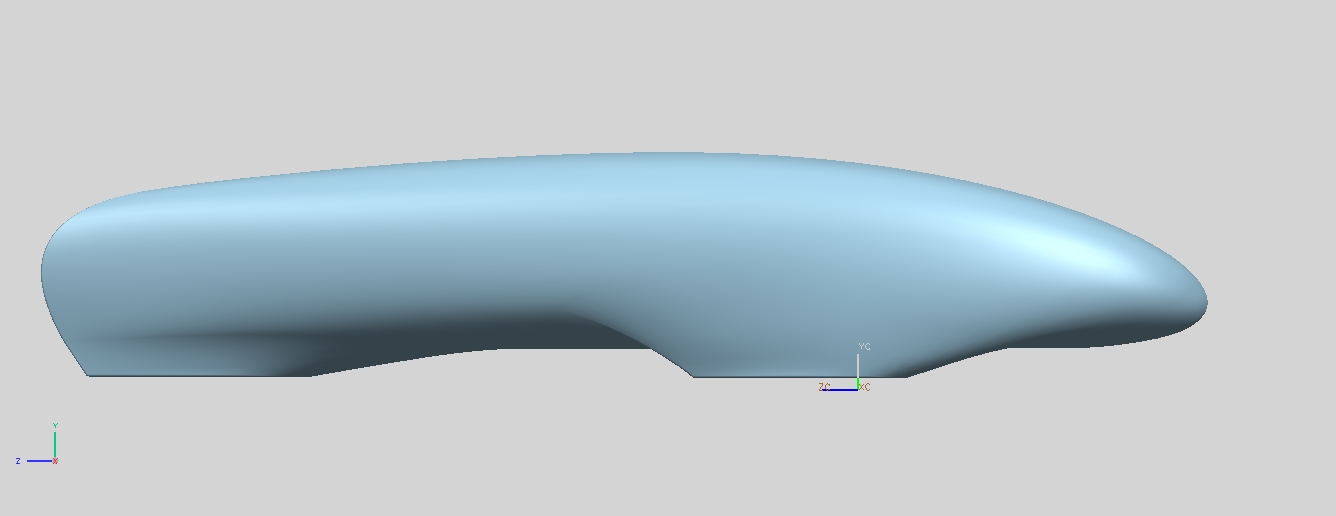
New hull
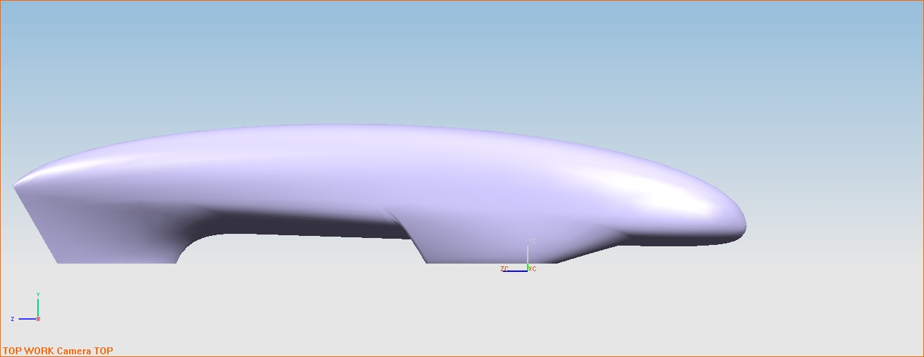
Old hull
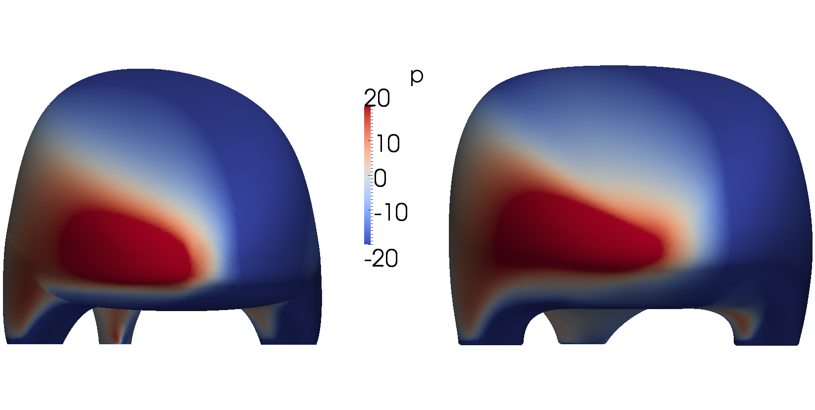
Finally, the frontal area of the hull had to be increased by 25% to meet the new constraints. However, the drag force has still been reduced by nearly 15%, which reduces the drag coefficient of approximately 30%.
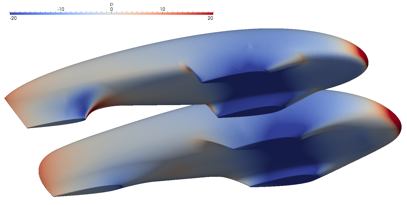
Comparison of the pressure distribution on the old shell (top) and the new hull (bottom)